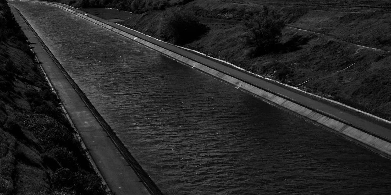
Canal Cross Section Generation with AutoPlotter CanSE
CanSE is equipped to define drains, dowels, spoil banks, service roads, lining & pitching, and other elements. CanSE can be efficiently used in new canal construction and re-surfacing and strengthening the existing canals also called modernization of canals.
Features for Canal cross section
Why Infycons is best for Canal Cross Section Software?
FAQ
Infycons AutoPlotter CanSE is the best for designing cross-section of a canal.
Canal irrigation is an effective means of irrigation that helps generate income for the government. It is the best way of irrigating infertile soil, helping the crops sustain the drought season, and covering a large area for irrigation.
Canal Cross-section is a cross-section diagram of a water channel that helps transfer water from the source to the fields or the target area. The cross-section of canals is taken for a better understanding of the underlying areas, the water level, and the nature of the soil. This information can be superimposed with new or modernization details to assist in construction and other related activities.
- Triangular section
- Rectangular section
- Trapezoidal section
- Circular section
Of all the above-mentioned types, a trapezoidal section and a combination of triangular with circular sections are the most suitable for a canal.
"*" indicates required fields


